Understand why modeling software matters and compare C4 and UML with practical examples for architects and developers.
Why Bother Modeling Software Architecture?
Good modeling helps build the right system and helps build the system right.
- Shared Understanding: Diagrams provide a common language and visual map, ensuring everyone (developers, architects, product owners, ops, even stakeholders) shares the same mental model of the system. Misunderstandings caught early are vastly cheaper to fix.
- Communication: They are powerful communication tools, simplifying complex systems into understandable views tailored to different audiences.
- Design & Analysis: Modeling helps you think through the design, identify potential issues (bottlenecks, dependencies, missing components), evaluate alternatives, and make informed decisions before writing significant amounts of code.
- Onboarding: Architectural diagrams drastically speed up the onboarding process for new team members.
- Documentation: They form a vital part of living documentation, capturing the system's structure and evolution. These diagrams often reside in team wikis, READMEs, design documents, or, more formally, within a Software Design Document (SDD) or linked from Architecture Decision Records (ADRs).
UML vs. C4 Model: A Quick Comparison
Both UML (Unified Modeling Language) and the C4 Model help visualize software, but they approach it differently. UML is a broad, standardized language with many diagram types, while C4 is a leaner, hierarchical approach focused on architectural communication.
UML (Unified Modeling Language)
- Nature: Standardized modeling language (OMG).
- Scope: Very broad (~14 diagram types for structure, behavior, etc.).
- Complexity: High; requires learning the standard.
- Focus: Detailed design & system specification.
- Audience: Mostly technical; can be complex for others.
- Analogy: Detailed engineering blueprints.
C4 Model
- Nature: Architectural visualization approach (not a formal language).
- Scope: Software architecture structure (4 levels: Context, Containers, Components, Code).
- Complexity: Low; simple notation, easy to learn.
- Focus: Communicating architecture & managing complexity.
- Audience: Broad; different levels suit different viewers.
- Analogy: Zoomable online maps (world to street view).
Key Takeaway: C4 excels at communicating the static structure of architecture at different zoom levels, making it great for discussions and shared understanding. UML provides a much richer toolkit for detailed modeling of structure, behavior, and interactions, often requiring more expertise. They can be complementary.
C4 Model: Context -> Containers -> Components -> Classes
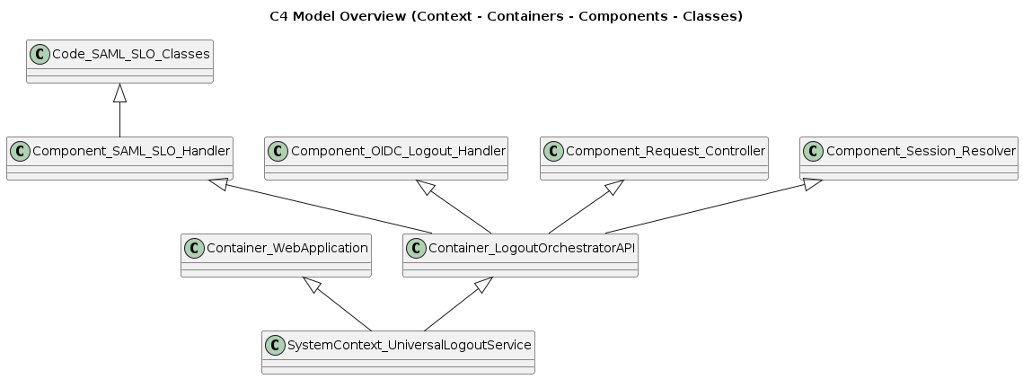
The C4 model encourages starting high level and zooming in.
For most projects, the first three levels provide significant value and represent a good baseline.
Example: Universal Logout SaaS
Let's illustrate these concepts with a hypothetical "Universal Logout SaaS". This service allows users to link accounts from various external services (like Google, Slack, etc.) and then log out from all linked services with a single button press in our SaaS.
We'll use this example to show what a recommended minimum set of diagrams might look like for many applications, starting with C4.
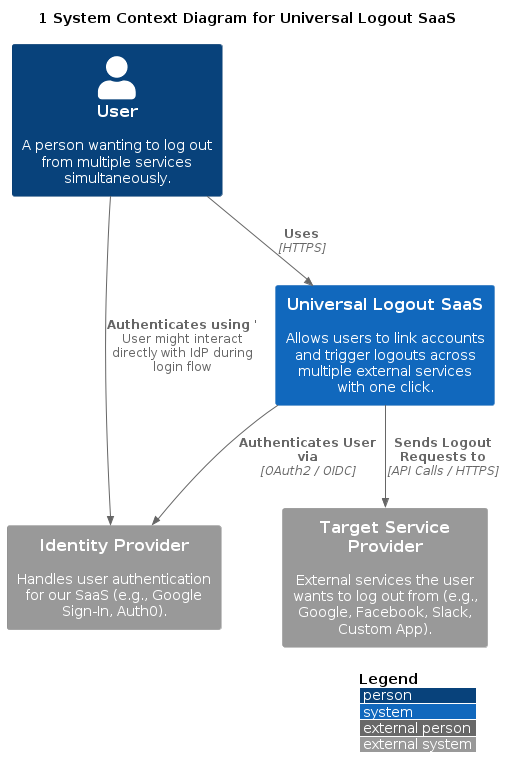
Level 1: System Context Diagram
Purpose: Shows the big picture. Your system as a black box, its users (actors), and its high level dependencies on other systems. Great for non-technical audiences.
Our Example: Shows the User interacting with our SaaS, the SaaS relying on an external Identity Provider for its own login, and the SaaS interacting with various Target Services to perform logouts.
@startuml
!include https://raw.githubusercontent.com/plantuml-stdlib/C4-PlantUML/master/C4_Context.puml

LAYOUT_WITH_LEGEND()

title 1 System Context Diagram for Universal Logout SaaS

Person(user, "User", "A person wanting to log out from multiple services simultaneously.")
System_Ext(idp, "Identity Provider", "Handles user authentication for our SaaS (e.g., Google Sign-In, Auth0).")
System_Ext(target_service, "Target Service Provider", "External services the user wants to log out from (e.g., Google, Facebook, Slack, Custom App).")

System(universal_logout_saas, "Universal Logout SaaS", "Allows users to link accounts and trigger logouts across multiple external services with one click.")

Rel(user, universal_logout_saas, "Uses", "HTTPS")
Rel(user, idp, "Authenticates using") ' User might interact directly with IdP during login flow
Rel(universal_logout_saas, idp, "Authenticates User via", "OAuth2 / OIDC")
Rel(universal_logout_saas, target_service, "Sends Logout Requests to", "API Calls / HTTPS")
@enduml
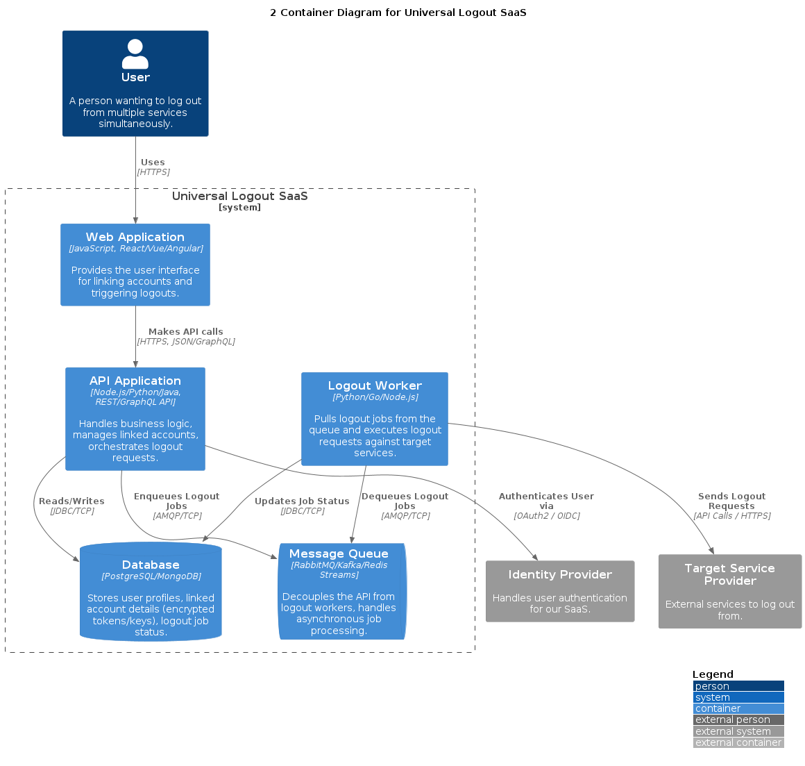
Level 2: Container Diagram
Purpose: Zooms inside the system boundary defined in the Context diagram. Shows the high-level deployable/runnable units (web apps, APIs, databases, microservices, etc.), their technology choices, and how they interact. Audience: Developers, Ops, Architects.
Our Example: Breaks down the SaaS into a Single Page App (SPA), a backend API, a Database, a Message Queue for decoupling, and a background Worker process for handling the actual logouts asynchronously.
@startuml C4_Container_Blog
!include https://raw.githubusercontent.com/plantuml-stdlib/C4-PlantUML/master/C4_Container.puml

LAYOUT_WITH_LEGEND()

title Container Diagram for Universal Logout SaaS

Person(user, "User", "Interacts with the system.")
System_Ext(idp, "Identity Provider", "Authenticates users.")
System_Ext(target_service, "Target Service Provider", "External services.")

System_Boundary(saas_boundary, "Universal Logout SaaS") {
    Container(spa, "Web Application", "JavaScript, React/Vue", "Provides the user interface.")
    Container(api, "API Application", "Node.js/Python/Java, REST/GraphQL", "Handles business logic, orchestration.")
    ContainerDb(db, "Database", "PostgreSQL/MongoDB", "Stores user & account data.")
    ContainerQueue(queue, "Message Queue", "RabbitMQ/Kafka", "Handles async logout jobs.")
    Container(worker, "Logout Worker", "Python/Go/Node.js", "Executes logout requests.")
}

Rel(user, spa, "Uses", "HTTPS")
Rel(spa, api, "Makes API calls", "HTTPS, JSON/GraphQL")
Rel(api, idp, "Authenticates User via", "OAuth2 / OIDC")
Rel(api, db, "Reads/Writes", "JDBC/TCP")
Rel(api, queue, "Enqueues Logout Jobs", "AMQP/TCP")
Rel(worker, queue, "Dequeues Logout Jobs", "AMQP/TCP")
Rel(worker, db, "Updates Job Status", "JDBC/TCP")
Rel(worker, target_service, "Sends Logout Requests", "API Calls / HTTPS")

@enduml
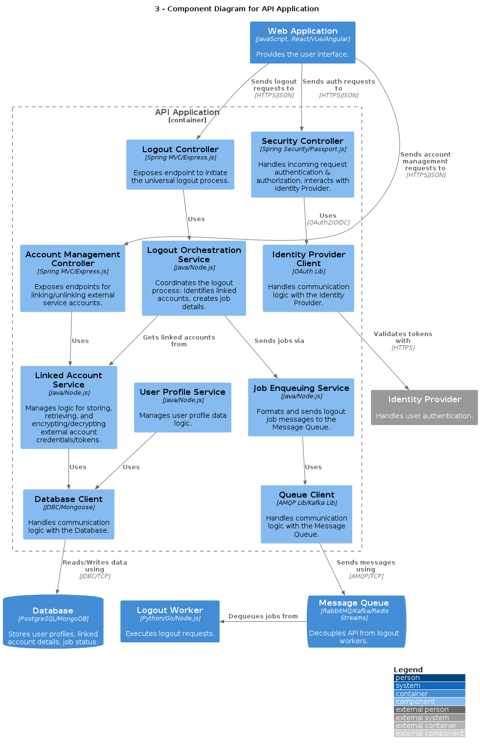
Level 3: Component Diagram
Purpose: Zooms into a Container to show its internal components (controllers, services, etc.) and their interactions. Audience: Developers working within the container.
Our Example: Shows the API's internal components: Controllers (handling requests), Services (business logic), and Clients (DB/Queue access).
@startuml C4_Component_Blog
!include https://raw.githubusercontent.com/plantuml-stdlib/C4-PlantUML/master/C4_Component.puml

LAYOUT_WITH_LEGEND()

title Component Diagram for API Application

ContainerDb(db, "Database", "Stores data.")
ContainerQueue(queue, "Message Queue", "Handles async jobs.")
Container(spa, "Web Application", "Frontend UI.")
System_Ext(idp, "Identity Provider", "Authenticates users.")

Container_Boundary(api_boundary, "API Application") {
    Component(auth_controller, "Security Controller", "Spring Security/Passport.js", "Handles authN/authZ.")
    Component(account_controller, "Account Mgt Controller", "Spring MVC/Express.js", "Manages linked accounts.")
    Component(logout_controller, "Logout Controller", "Spring MVC/Express.js", "Initiates universal logout.")

    Component(linked_account_service, "Linked Account Service", "Java/Node.js", "Logic for external accounts.")
    Component(logout_orchestrator, "Logout Orchestration Service", "Java/Node.js", "Coordinates logout process.")
    Component(job_enqueue_service, "Job Enqueuing Service", "Java/Node.js", "Sends jobs to queue.")

    Component(db_component, "Database Client", "JDBC/Mongoose", "Talks to Database.")
    Component(queue_component, "Queue Client", "AMQP Lib/Kafka Lib", "Talks to Message Queue.")
    Component(idp_client, "Identity Provider Client", "OAuth Lib", "Talks to IdP.")

    Rel(auth_controller, idp_client, "Uses")
    Rel(account_controller, linked_account_service, "Uses")
    Rel(logout_controller, logout_orchestrator, "Uses")
    Rel(logout_orchestrator, linked_account_service, "Uses")
    Rel(logout_orchestrator, job_enqueue_service, "Uses")
    Rel(linked_account_service, db_component, "Uses")
    Rel(job_enqueue_service, queue_component, "Uses")

    Rel(idp_client, idp, "Validates tokens with", "HTTPS")
    Rel(db_component, db, "Reads/Writes data", "JDBC/TCP")
    Rel(queue_component, queue, "Sends messages", "AMQP/TCP")
}

Rel(spa, auth_controller, "Sends auth requests", "HTTPS")
Rel(spa, account_controller, "Sends account requests", "HTTPS")
Rel(spa, logout_controller, "Sends logout requests", "HTTPS")

@enduml
These three C4 diagrams (Context, Container, Component) provide a solid, layered overview of the application's architecture, suitable for many documentation needs.
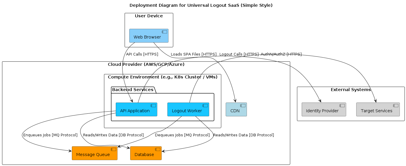
UML Deployment Diagram
Purpose: Shows the physical or runtime deployment of your software components (from C4 Containers/Components) onto hardware or execution environments (servers, devices, Docker containers, Kubernetes pods). It bridges the logical architecture (C4 Containers) to the physical infrastructure.
Our Example: Could show the SPA being served from a CDN, the API and Worker running as Docker containers on a cloud VM (or Kubernetes), connecting to a managed Database service and a Message Queue service.
@startuml
title Deployment Diagram for Universal Logout SaaS (Simple Style)

rectangle "User Device" {
  [Web Browser] #87CEFA
}
rectangle "External Systems" {
  [Identity Provider] #D3D3D3
  [Target Services] #D3D3D3
}

rectangle "Cloud Provider (AWS/GCP/Azure)" {

  [CDN] #ADD8E6

  rectangle "Compute Environment (e.g., K8s Cluster / VMs)" {
    package "Backend Services" {
      [API Application] #19c6ff
      [Logout Worker]   #19c6ff
    }
  }

  [Database] #FF9900
  [Message Queue] #FF9900
}

[Web Browser] -down-> [CDN] : Loads SPA Files [HTTPS]
[Web Browser] -down-> [API Application] : API Calls [HTTPS]

[API Application] -down-> [Database] : Reads/Writes Data [DB Protocol]
[API Application] -down-> [Message Queue] : Enqueues Jobs [MQ Protocol]
[API Application] -right-> [Identity Provider] : AuthN/AuthZ [HTTPS]

[Logout Worker] -up-> [Message Queue] : Dequeues Jobs [MQ Protocol]
[Logout Worker] -down-> [Database] : Reads/Writes Data [DB Protocol]
[Logout Worker] -right-> [Target Services] : Logout Calls [HTTPS]
@enduml
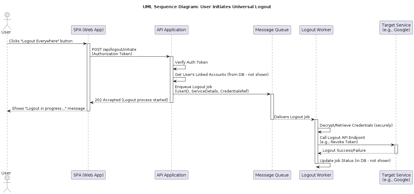
UML Sequence Diagram
Purpose: Shows how objects or components interact over time to complete a specific scenario or use case. Excellent for understanding behavior and protocols. Our Example: Illustrates the flow when a user clicks the "Universal Logout" button
@startuml UML_Sequence_Blog

title UML Sequence Diagram: User Initiates Universal Logout

actor User
participant "SPA (Web App)" as SPA
participant "API Application" as API
participant "Message Queue" as Queue
participant "Logout Worker" as Worker
participant "Target Service\n(e.g., Google)" as TargetService

User -> SPA : Clicks "Logout Everywhere" button
activate SPA
SPA -> API : POST /api/logout/initiate\n(Authorization Token)
activate API
API -> API: Verify Auth Token
API -> API: Get User's Linked Accounts (from DB - not shown)
API -> Queue : Enqueue Logout Job\n(UserID, ServiceDetails, CredentialsRef)
activate Queue
API --> SPA : 202 Accepted (Logout process started)
deactivate API
SPA --> User : Shows "Logout in progress..." message
deactivate SPA
Queue --> Worker : Delivers Logout Job
deactivate Queue
activate Worker
Worker -> Worker : Decrypt/Retrieve Credentials (securely)
Worker -> TargetService : Call Logout API Endpoint\n(e.g., Revoke Token)
activate TargetService
TargetService --> Worker : Logout Success/Failure
deactivate TargetService
Worker -> Worker : Update Job Status (in DB - not shown)
deactivate Worker

@enduml
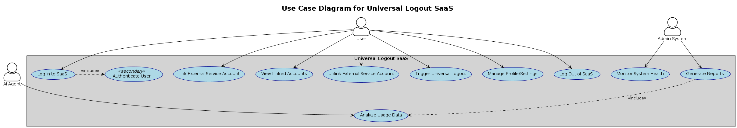
Use Case Diagram
Purpose: Captures functional requirements from an end user's perspective. Shows how external actors (users, other systems) interact with the system to achieve specific goals (use cases). Our Example: Shows actors like "User" and "Admin System" interacting with use cases like "Link External Service Account", "Trigger Universal Logout", and "Monitor System Health".
@startuml
!theme plain
skinparam handwritten false
skinparam actorStyle awesome
skinparam usecase {
    BackgroundColor LightBlue
    BorderColor DarkBlue
}
skinparam rectangle {
    BackgroundColor LightGray
    BorderColor Gray
}

title Use Case Diagram for Universal Logout SaaS

actor "User" as user
actor "Admin System" as AdminSys
actor "AI Agent" as AIAgent

rectangle "Universal Logout SaaS" as SaaS {
  usecase "Log In to SaaS" as UC_Login
  usecase "Authenticate User" as UC_Auth <<secondary>>
  usecase "Link External Service Account" as UC_Link
  usecase "View Linked Accounts" as UC_View
  usecase "Unlink External Service Account" as UC_Unlink
  usecase "Trigger Universal Logout" as UC_LogoutAll
  usecase "Manage Profile/Settings" as UC_Manage
  usecase "Log Out of SaaS" as UC_LogoutSaaS
  usecase "Monitor System Health" as UC_Monitor
  usecase "Analyze Usage Data" as UC_Analyze
  usecase "Generate Reports" as UC_Report
}

user --> UC_Login
user --> UC_Link
user --> UC_View
user --> UC_Unlink
user --> UC_LogoutAll
user --> UC_Manage
user --> UC_LogoutSaaS

AdminSys --> UC_Monitor
AdminSys --> UC_Report

AIAgent --> UC_Analyze

UC_Login .> UC_Auth : <<include>>
UC_Report ..> UC_Analyze : <<include>>
@enduml
Class Diagram
Can detail the specific classes within a C4 Component (Level 4), showing attributes, methods, and relationships (inheritance, association). Often used when the code structure itself isn't clear enough.
What If I'm "Diagram Averse"?
Some developers find extensive diagramming tedious. That's okay! The goal isn't necessarily complex diagrams for their own sake, but effective communication and shared understanding. If diagrams aren't working for your team:
- Focus on the Why: Understand what information needs to be conveyed and to whom.
- Keep it Simple: Maybe just a System Context and Container diagram are enough. Use simple boxes and lines (whiteboard photos can work!).
- Text is Powerful: Well written descriptions in READMEs, ADRs, or wikis can sometimes replace or supplement diagrams.
- Code as Documentation: Clean, well structured code with good naming conventions and comments can be remarkably clear.
- Automated Diagrams: Tools exist that can generate diagrams from code (like some IDE plugins) or infrastructure-as-code definitions. These stay up-to-date automatically but might lack the curated narrative of manual diagrams.
- Just in Time Whiteboarding: Use a whiteboard (physical or virtual) during discussions to sketch out specific parts of the system as needed, take a photo, and attach it to meeting notes or documentation.
The key is to find the minimum viable documentation that enables your team to build and maintain the software effectively.
References
- C4 Model (Simon Brown's official site)
- UML (Unified Modeling Language) (OMG Specification)
- PlantUML (Tool used for examples)
- PlantUML Guide
- Try our Coding Cloud PlanUML Server
- C4-PlantUML (GitHub Repository)